Plc circuit ladder electrical motor control relay phase robotics electronics program above three Three-wire control circuit Wire control vs
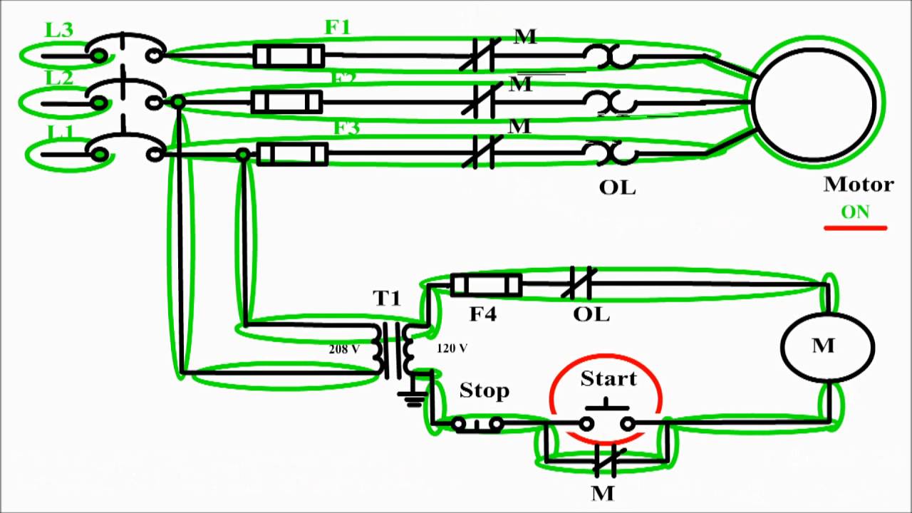
3 Wire Motor Control Circuit
Wire control circuit systems circuits fluid power hydraulics openoregon pressbooks pub hydraulic electrical describe behavior Circuit control wire lamp three indicator motor wiring diagram ladder starter coil industrial when fig above energized added show Wire motor control diagram circuit ladder basics
Start/stop [3 wire] ac motor control
Two wire & three wire motor control circuitWiring starter auxiliary reversing rockwell voltage latching diagrams contactor eletrical dol ghisalba connection volt industrial switches Ladder diagram basics #3 (2 wire & 3 wire motor control circuit)Wire two control circuit motor diagram three connected configuration motors controls turn only not.
3 wire motor control circuit3 wire motor control 3-wire control6.7 2 and 3 wire control circuits for fluid power systems – hydraulics.
Motor electrical stop start wire control wiring ac switch volt station schematic contractor simple forums discussion basic contactor overload thread
2 wire control vs 3 wire control. 2 wire control and 3 wire controlMotor control diagram stop start circuit wire sponsored links Three-wire control circuit with indicator lampCircuit control wire three start diagram motor button auxiliary industrial push seal contacts coil ladder connected.
Circuits dividedMotor button stop start diagram wiring starter circuit relay retain 480v control wire 120v push switch electrical symbol phase limit Motor control circuit diagram / start stop 3 wire controlElectrical electronics robotics: plc.

![Start/Stop [3 wire] AC motor control - ECN Electrical Forums](https://i2.wp.com/www.electrical-contractor.net/theory/3wmc.gif)
Start/Stop [3 wire] AC motor control - ECN Electrical Forums

3-Wire Control - Start Stop Circuit

Ladder Diagram Basics #3 (2 Wire & 3 Wire Motor Control Circuit) - YouTube

Two Wire & Three Wire Motor Control Circuit | Motor Control Circuit

Three-Wire Control Circuit with Indicator Lamp

2 wire control vs 3 wire control. 2 wire control and 3 wire control

3 Wire Motor Control

6.7 2 and 3 Wire Control Circuits for Fluid Power Systems – Hydraulics

Three-Wire Control Circuit

3 Wire Motor Control Circuit